From CAD to Medical Device Compliance: Developing a Safety Handset

Regner® Editorial Team
Aiguaviva -
16/09/2026
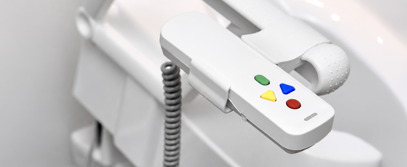
Mando de control IP67 desarrollado por REGNER para el eTSE de Drive Medical con actuador lineal RA42

REGNER® developed the control handset for Drive Medical’s eTSE Toilet Stand-up Aid, which incorporates the RA42 linear actuator. This article explores the engineering decisions behind the system, including ergonomics for users with reduced hand strength, contact debounce filtering, IP67 sealing with a single gasket, poka yoke assembly tooling and technical documentation in accordance with ISO 14971 and IEC 62366-1.

mando de control IP67 para dispositivo médico

Designing a four button control handset may seem like a minor part of an electromechanical system. In reality, it is precisely where many engineering decisions come together: ergonomics, mechanics, electronics, software, power management, cabling, environmental protection and manufacturing.

Drive Medical’s eTSE is a powered toilet stand up aid. It progressively raises and tilts the seat to help people with reduced mobility stand up with less physical effort. Our RA42 linear actuator generates this movement. But generating the movement alone did not solve the product.

As Head of R&D, I knew that the real challenge was determining how a vulnerable user could control the system simply and intuitively, and how that interaction could be turned into a robust subsystem that we could manufacture, verify and document without leaving room for error. That was the engineering challenge behind the 190000 control handset.

1. Technical specifications of the 190000 handset

Parameter Value
Button diameter 18 mm
Movement button relief 1.2 mm
Actuation force 3.5 N
Tactile travel 1.5 mm
Software debounce 25 ms
Battery Li-ion 11.1 V / 2.2 Ah (24.42 Wh)
Coiled cable PUR · 500 mm → 1,800 mm
Maximum pulling force on the hand 8 N
Cable strain relief fatigue test 15,000 cycles at 90°
Handset protection rating IP67 (IEC 60529)
eTSE connector Industrial circular, IPX7
Associated actuator RA42

2. Ergonomics and human factors: designing the interaction before the handset

When developing a device that is operated by hand, the first question is not where to position the PCB. It is who will use the device, what they need to do and under what conditions. Within the human factors engineering framework defined by IEC 62366-1, we work with three variables: the user, the environment and the interface. The typical user of the 190000 handset may have arthritis, reduced grip strength or impaired vision. For this reason, the four main functions were clearly differentiated through colour and geometry: green to activate the system, red to switch off and stop, yellow to raise and blue to lower.

Why 18 mm and 3.5 N

We specified an 18 mm button diameter, with a 1.2 mm concave profile on the movement buttons. This helps guide the fingertip naturally towards the centre without requiring the user to look at the handset. We also defined an actuation force of 3.5 N with 1.5 mm of tactile travel. This combination is deliberate. An actuation force of 3.5 N is light enough for a weakened hand to operate without fatigue, while remaining firm enough to prevent unintended activation if the handset is placed face down or accidentally pressed against the thigh support.

Three housing geometries rejected before finding the right one

We evaluated three housing geometries using 3D printed prototypes. The first, visually elegant oval design was rejected because it required the hand to open too widely. A second, flatter version was discarded because it became difficult to hold securely with wet hands. We ultimately selected an elongated body with an anatomically contoured rear surface. This makes the handset easier to hold with one hand and allows it to slide naturally into the eTSE holder without requiring the user to find a precise insertion angle.

3. From electrical signal to movement: control electronics and firmware

For the user, pressing the yellow button simply means “raise”. For our electronics and firmware teams, that is where the control logic begins. The 190000 handset integrates the control PCB, power management system, rechargeable Li ion battery at 11.1 V / 2.2 Ah and 24.42 Wh, together with our proprietary firmware. At hardware level, mechanical contacts inevitably produce contact bounce. We implemented a combined filtering strategy consisting of an RC filter on the button input lines together with a 25 ms software debounce routine in the firmware. This ensures that any disturbance or tremor in the user’s hand is interpreted as a single, clean command before the RA42 power stage is energised.

Four critical faults, one clear signal for the user

The handset detects four critical fault conditions:
No. Detected fault
1 Voltage drop caused by a low battery
2 Actuator overcurrent caused by a mechanical obstruction
3 Cell degradation or charging cycle failure
4 Actuator disconnection
For the user, the LED array simplifies the situation by displaying a single flashing red pattern indicating a system fault. For service technicians, however, the firmware stores the fault code in non volatile memory and provides a coded diagnostic flashing sequence when the green button is held for five seconds. Translating technical complexity into a clear user response is what prevents unnecessary calls to technical support.

4. Mechanical integration: PCB, battery and cabling within a minimal volume

The classic challenge of compact mechatronics is making everything fit and, more importantly, ensuring that it can be assembled consistently in series production without placing stress on any component. Inside the housing, the main PCB, battery pack, charging connector and cable glands all have to coexist within a very limited space. We completed four major functional prototyping iterations. During the second iteration, we identified a critical issue that had not been anticipated in the CAD model. The internal battery connector collided with one of the housing’s threaded bosses when the enclosure was closed. This placed stress on the wiring harness and prevented uniform sealing. We redesigned the PCB, moving the charge management stage to the rear side, and repositioned the battery on a rigid internal chassis that serves both as a structural support and as a guide for the cabling. This change created exactly the clearance required to allow the housing to be closed vertically on the assembly line without placing stress on any internal component.

5. PUR coiled cable and strain relief: when a cable forces a product redesign

The coiled cable is not simply an accessory. It is a structural element subjected to continuous mechanical fatigue. We selected a cable with a polyurethane, PUR, outer jacket with high elastic memory instead of conventional PVC. In a bathroom environment, PVC can deteriorate more quickly when exposed to household cleaning products and gradually lose its ability to retract. The cable measures 500 mm at rest and extends to 1,800 mm without exerting more than 8 N of pulling force on the user’s hand. For strain relief, we designed an overmoulded flexible elastomer component with a graduated conical profile at the housing outlet. We subjected the joint to 15,000 bending cycles under a dynamically deflected load at 90° to ensure that the internal copper conductors did not develop fatigue microfractures. For connection to the eTSE base unit, we selected an industrial circular connector with an IPX7 protection rating.

6. IP67 protection: what it means and how it shapes the product architecture

Mando de control IP67 para dispositivo médico

What IP67 means

IP67 is the protection rating defined by IEC 60529 that combines complete protection against dust ingress, represented by the first digit 6, with resistance to temporary immersion in water at a depth of up to 1 metre for 30 minutes, represented by the second digit 7.

The eTSE operates in a wet environment by definition. Achieving this level of protection is not a matter of adding silicone at the end of the development process. It has to be considered from the very first CAD decisions.

A single compression line Our starting decision was to reduce the sealing problem to a single closure zone. Instead of solving the housing seal, each individual button and the cable outlet separately, we designed a single silicone gasket integrated with the buttons that runs around the entire perimeter of the handset. It follows the same principle used in sealed IP67 enclosures: one continuous compression line. Fewer interfaces mean fewer variables to control and a single critical parameter to verify on the assembly line.
To achieve the required sealing performance of the IP67 control handset:
The perimeter gasket and the membranes of the four buttons form a single component. There are no separate through buttons with clearances or cavities that need to be sealed individually. The gasket itself seals the assembly while transmitting the button movement.

Controlled gasket compression is maintained around the entire housing perimeter, preventing areas of insufficient compression at the corners and around the fixing bosses.

The cable outlet uses a custom designed cable gland located within, a sealed cavity integrated into the housing itself and positioned inside the same perimeter compression line.

Mechanical cable retention is structural and does not depend on the seal. The two halves of the housing clamp the body of the cable gland when closed. Any accidental pull on the cable is therefore transferred to the housing structure rather than to the gasket or the PCB solder joints.
Validation in accordance with IEC 60529 We validated the system in accordance with IEC 60529 by subjecting the handsets to the IP6X dust tightness test and the IPX7 water immersion test at a depth of 1 metre for 30 minutes. After testing, we verified that there was no moisture or trace of dust on the PCB or inside the battery compartment.

7. Industrialisation: poka yoke tooling and 100% functional verification

util para mando de control IP67 para dispositivo médico
util_e-TSE_190000_handset.jpg
A functional prototype only proves that you were able to build one. Industrialisation means designing the processes and tooling required to ensure that the 1,000th unit can be assembled in the same time and to the same quality standard as the first. For the 190000 handset, we developed dedicated in line assembly tooling that positions the silicone membrane and PCB in only one correct orientation, applying error proofing or poka yoke principles. The assembly sequence is defined in four standardised steps, without requiring parts to be inverted during the process. We also designed a 100% end of line functional verification station. Before the shipping box is closed, every handset is connected to an automated tester that verifies:
No. Test bench verification
1 Current consumption in sleep mode and during charging
2 Force / impedance response of the four buttons
3 Charge-discharge cycle and battery indicator calibration
4 Communication with the RA42 actuator using a simulated load

8. Regulatory compliance: MDR 2017/745 and subsystem technical documentation

The handset forms part of a medical device. Every engineering decision therefore had to be justified, assessed and documented. As the legal manufacturer of the final product, Drive Medical is responsible for declaring the eTSE’s conformity with Regulation (EU) 2017/745, the Medical Device Regulation, MDR, and with DIN EN ISO 17966. To support this process, REGNER supplied the complete technical documentation for our subsystem.
Document Reference standard
Risk management analysis ISO 14971
Usability evaluation and human factors engineering IEC 62366-1
Electromagnetic compatibility (EMC) testing IEC 60601-1-2
Ingress protection testing IEC 60529
In this sector, usability is not an abstract concept. A confusing button or an incorrect light indication can translate directly into a clinical risk that must be mitigated through design.

Complete engineering in support of the user experience

The true scale of the development behind the 190000 handset only becomes apparent when you look beneath the surface. Ergonomics, electronics, software, IP67 protection, cabling, industrialisation and regulatory requirements are all part of the same development process. Each discipline affects the others, and all of them must converge in a product that users can operate without having to think about the complexity behind it. The RA42 linear actuator provides the movement required by the eTSE. The 190000 handset turns that movement into a controllable, integrated and safe function. That is what going beyond the actuator means to us at REGNER: not simply generating movement, but developing the engineering required to integrate that movement into the final product.
producto sanitario

VISIT THE FOLLOWING ARTICLE:

Share this post!

×ATENCIÓ: Cookies no configurades en l'idioma actual. Revisa la teva configuració al plugin, gràcies!